-
E-mail
office55@silkroad24.com
-
Phone
18964582625
-
Address
Building 1034-1035, No. 999 Wangqiao Road, Chuansha, Pudong New Area
Product Categories
Xierko Trading (Shanghai) Co., Ltd
Dynisco Pressure Sensor SPX2 Series
NegotiableUpdate on 02/21
- Model
- Nature of the Manufacturer
- Producers
- Product Category
- Place of Origin
Overview
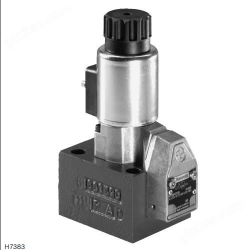
The Dynisco SPX2 series is a high-performance and highly reliable pressure transmitter designed specifically for operation in hazardous environments. Its intelligent features, multiple certifications, and wide applicability make it an ideal choice in the fields of industrial automation and process control. The SPX2 series is an intelligent pressure transmitter that can be directly connected to distributed control systems (DCS), programmable logic controllers (PLC), and computers. $r $nDynisco Pressure Sensor SPX2 Series XiErKe
Product Details
The Dynisco SPX2 series is a high-performance and highly reliable pressure transmitter designed specifically for operation in hazardous environments. Its intelligent features, multiple certifications, and wide applicability make it an ideal choice in the fields of industrial automation and process control.
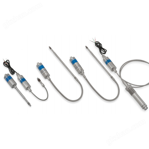
Dynisco Pressure Sensor SPX2 Series
Dynisco Pressure Sensor SPX2 Series
Main Features
Intelligent pressure transmitter
The SPX2 series is an intelligent pressure transmitter that can be directly connected to distributed control systems (DCS), programmable logic controllers (PLC), and computers.
Support remote configuration through the HART protocol, making it convenient for users to adjust parameters and monitor.
Applicability to hazardous locations
ATEX and IECEx intrinsic safety certifications
FM and CSA explosion-proof certification
SIL 2 certification (pressure output)
PL'c 'certification (relay output)
Suitable for hazardous locations and compliant with multiple international certifications, including:
high-precision measurement
The accuracy range is from ± 0.25% to ± 1.0%, depending on the model and pressure range.
Provide optional thermocouple or RTD configurations for measuring melt temperature.
Wide pressure range
We offer a variety of pressure range options, from 25 psi to 30000 psi (0.175 MPa to 200 MPa), to meet different application needs.
With a range ratio of 6:1 (SPX2290 model 3:1), it supports flexible measurement range adjustment.
environmental adaptability
The working temperature range is -29 ° C to 85 ° C (for electronic components), and some models of membranes can reach temperatures as high as 400 ° C (600 ° F).
Under temperature changes, it has small zero and range drift.
Anti overvoltage capability
The overvoltage protection range is 2 times the full range output (FSO) or 35000 psi (whichever is smaller), SPX2290、 Models 2291 and 2292 are 1.5 times FSO.
Installation and maintenance
Provide multiple installation options, including flanges, threaded connections, etc.
All models support direct installation and have low maintenance requirements.
Technical Specifications
output signal
4-20mA loop power output, optional HART protocol.
input voltage
The standard input voltage is 16-36 Vdc, and the ATEX intrinsic safety model is 16-30 Vdc.
precision
SPX2241:±1.0%
SPX2242: ± 0.25% (pressure range ≥ 1500 psi), ± 0.50% (pressure range<1500 psi)
SPX2243: ± 0.25% (pressure range ≥ 1500 psi), ± 0.50% (pressure range<1500 psi)
SPX2244: ± 0.25% (pressure range ≥ 500 psi), ± 1.0% (pressure range<500 psi)
SPX2290/2291/2292:±0.50%
Accuracy is defined as the percentage error of full-scale output (FSO), as follows:
repetitiveness
±0.1%
turndown ratio
6: 1 (SPX2290 model is 3:1)
Overvoltage protection
2 times FSO or 35000 psi (whichever is smaller), SPX2290、 Models 2291 and 2292 are 1.5 times FSO.
Zero balance adjustment range
-40% to+10%; For models with FSO<500 psi, the adjustment range is -80% to+20%.
load resistor
500Ω@24Vdc,1000Ω@36Vdc。
Operating Temperature
The working temperature range of electronic components is -29 ° C to 85 ° C (-20 ° F to 185 ° F).
The maximum temperature of the membrane can reach 400 ° C (750 ° F), but some models (such as 2241, 2244, 2290, 2291, 2292) are limited to 315 ° C (600 ° F).
Temperature compensation range
The temperature compensation range for electronic components is 0 ° C to 65 ° C (-18 ° F to 150 ° F).
Zero point and range drift
Zero drift: 0.01% F.S./° F (0.02% F.S./° C).
Range drift: 0.01% F.S./° F (0.02% F.S./° C).
mechanical properties
Provide multiple installation torque options to meet different installation requirements.
The material of the wet parts is DyMax coated 15-5 PH stainless steel (SST).
Certification and Compliance
International Certification
ATEX and IECEx intrinsic safety certifications
FM and CSA explosion-proof certification
SIL 2 certification (pressure output)
PL'c 'certification (relay output)
CE Certification
Other Compliance
Compliant with CE requirements and suitable for industrial environments.
Brand:Dynisco
series:SPX2
Product Name: Pressure Sensor
1. Approval (certification)
·E=Explosion Proof
·This model has passed the explosion-proof certification and is suitable for hazardous environments with explosive gases or dust.
·S=ATEX/Intrinsically Safe
·Indicates that the model complies withATEX certification and intrinsic safety features, suitable for flammable and explosive environments.
·N=No approvals
·This model does not have any special safety certification.
2. Diaphragm Material
·A = DyMax Coated 15-5 PH SST
·Standard configuration, usingThe 15-5 PH stainless steel membrane coated with DyMax has excellent corrosion resistance and mechanical strength.
·M = Hastelloy
·Optional configuration,Hastelloy alloy membrane, suitable for corrosive environments.
·P = Inconel
·Optional configuration,Inconel alloy diaphragm, suitable for high temperature and high pressure working conditions.
3. Process Connection
·00 = 1/2-20 UNF
·Standard threaded connection, suitable for most industrial applications.
·05 = M18 x 1.5 Thread
·Metric threaded connections are suitable for application scenarios that require standardized interfaces.
4. Pressure Units
·B = BAR
·C = kPa
·K = Kgf/cm²
·M = MPa
·P = PSI
·Provide multiple pressure unit options for easy adaptation to different application scenarios.
5. Pressure Range
·13 = 250 psi / 17.5 Bar / 17.5 kgf/cm² / 1.75 MPa
·14 = 500 psi / 35 Bar / 35 kgf/cm² / 3.5 MPa
·15 = 750 psi / 50 Bar / 50 kgf/cm² / 5.0 MPa
·16 = 1,000 psi / 70 Bar / 70 kgf/cm² / 7.0 MPa
·17 = 1,500 psi / 100 Bar / 100 kgf/cm² / 10.0 MPa
·20 = 3,000 psi / 200 Bar / 200 kgf/cm² / 20.0 MPa
·21 = 5,000 psi / 350 Bar / 350 kgf/cm² / 35.0 MPa
·22 = 7,500 psi / 500 Bar / 500 kgf/cm² / 50.0 MPa
·23 = 10,000 psi / 700 Bar / 700 kgf/cm² / 70.0 MPa
·24 = 15,000 psi / 1,000 Bar / 1,000 kgf/cm² / 100.0 MPa
·25 = 20,000 psi / 1,400 Bar / 1,400 kgf/cm² / 140.0 MPa
·27 = 30,000 psi / 2,000 Bar / 2,000 kgf/cm² / 200.0 MPa
·Provide a wide range of range options to meet measurement needs from low pressure to ultra-high pressure.
6. Snout Length (probe length)
·AW = 3” (7.6 cm)
·CE = 6” (15 cm)
·DP = 9” (23 cm)
·FE = 12.5” (32 cm)
·GH = 15” (38 cm)
·The probe length is selected according to the installation environment and process requirements to ensure accurate pressure measurement.
7. Flex Length
·AA=No Flex
·DD = 18” (46 cm) Flex
·FF = 30” (76 cm) Flex
·The length of flexible cables can be flexibly adjusted according to on-site wiring requirements to improve installation convenience.
8. Communications (Communication Protocol)
·A=No Protocol
·B = HART™ Protocol
·supportThe HART protocol enables digital communication, facilitating remote configuration, diagnosis, and data collection.
9. Electrical Connections
·AC = PT1H-10-6P Connector
·standard6-pin connector, suitable for most industrial equipment.
·CA = 1/2-14 NPT Conduit with 42” Leads
·NPT conduit connection with 42 inch lead, suitable for occasions requiring sealed wiring.
·AF = PCIH-12-8P Connector Threaded Style
·8-pin threaded connector provides higher protection level and stability.
10. Temperature Sensor
·ZZ=No Thermocouple/RTD (without temperature sensor)
·AA = Single J TC with 3” Flex
·Optional individualJ-type thermocouple with 3-inch flexible cable for measuring melt temperature.
11. Option Code
·Option Code is a customizable field used to specify specific configurations or features. For example:
·Special calibration requirements
·Material Customization
·Special coating
·Install accessories, etc

Similar Product Recommend