Welcome Customer !

Membership

Help

Jiangsu Sanfeng Instrument Technology Co., Ltd
Custom manufacturer

Main Products:

intelligent-mfg>Products

Jiangsu Sanfeng Instrument Technology Co., Ltd

  • E-mail

    sfybkj@163.com

  • Phone

    18915199993

  • Address

    No. 8-6 Kejian Road, Dailou Industrial Park, Jinhu County, Jiangsu Province

Contact Now

Price of metal tube rotor flowmeter

NegotiableUpdate on 06/11
Model
Nature of the Manufacturer
Producers
Product Category
Place of Origin

Overview

Brief description: The metal tube rotor flowmeter has a simple price structure, reliable operation, high accuracy, and a wide range of applications. Compared with glass rotor flow meters, it can withstand higher pressures. It has varieties such as on-site indication, remote transmission, limit switch alarm, corrosion resistance, jacket type, damping type, and explosion-proof. Widely used in the measurement and automatic control of liquid and gas flow in departments such as national defense, chemical industry, petroleum, metallurgy, power, environmental protection, medicine, and light industry.

Product Details

JiangsuPrice of metal tube rotor flowmeter

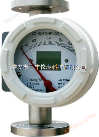
Price of metal tube rotor flowmeterIt is a metal structure float flowmeter suitable for measuring liquids and gases. The float moves upward under the action of fluid and buoyancy, and after balancing with the weight of the float, it is transmitted to the dial through magnetic coupling to indicate the corresponding flow rate, which can output a 4-20mA electrical signal.

Metal tube rotor flowmeterThe HXF series metal tube float flowmeter with a sturdy structural design can be widely used in flow measurement processes for complex, harsh environmental conditions and various media.
Protection level: 1P65
Material: Stainless steel PTFE
Work pressure: 1.6-4.0MPa
Environmental temperature: -25 ℃ -+65 ℃
Full stainless steel case, aluminum alloy case, contactless and non transmission mechanism ESK transmitter 4-20mA electrical signal output, two-wire inductive limit switch

IITechnical Parameter

orifice

(mm)

Flow range

Pressure loss KPa

Water L/h

Air m3/h

water

air

Conventional type

Anticorrosive type

Conventional/anti-corrosion type

Conventional type

Anticorrosive type

15

2.5-25
4.0-40
6.3-63
10-100
16-160
25-250
40-400
63-630

2.5-25
4.0-40
6.3-63
10-100
16-160
25-250
40-400

0.07-0.7
0.11-1.1
0.18-1.8
0.28-2.8
0.48-4.8
0.7-7.0
1.0-10.0
1.6-16.0

6.5
6.5
6.6
6.6
6.8
7.0
8.6
11.1

5.5
5.5
5.6
5.6
5.8
6.1
7.3

7.1
7.2
7.3
7.5
8.0
10.8
10.0
14.0

25

100-1000
160-1600
250-2500
400-4000

63-630
100-1000
160-1600
250-2500

3-30
4.5-45
7-70
11-110

7.0
8.0
10.8
15.8

5.9
6.0
6.8
9.2

7.7
8.8
12.0
19.0

50

630-6300
1000-10000
1600-16000

400-4000
630-6300
000-10000

18-180
25-250
40-400

8.1
11.0
17.0

6.8
9.4
14.5

8.6
10.4
15.5

80

2500-25000
4000-40000

1600-16000
2500-25000

60-600
80-800

8.1
9.5

6.9
8.0

12.9
18.5

100

6300-63000

4000-40000

100-1000

15.0

8.5

19.2

150

20000-100000

600-3000

19.2

20.

Model specification table

Specification code describe
Factory logo SF Jiangsu Sanfeng Instrument Technology Co., Ltd
Instrument type F Metal tube float flowmeter
Path code —XXX Example: 15 represents DN15
structural style A Down in, up out
B Up and down, out
C Near side measurement
D Bottom in and side out
R Right in, left out
L Left in and right out
K Clamp (sanitary polishing tube)
W threaded
Measurement tube material R1 1Cr18Ni9Ti,304
R0 0cr18Ni12M02Ti,316
RL 316L
RP PTFE (PTFE lined)
Ni Hasloy (Hastelloy C)
Ti TitHXium (titanium alloy)
Media Type L liquid
G gas
operation temperature H1 —40℃-100℃
H2 —80℃-250℃
Rated pressure 1.6 1.6MPa
4 4.0MPa
16 16MPa
25 25MPa
additional structure O not have
Z Damping type
T Jacket type
H High temperature type
Y High pressure
Indicator form M1 On site instruction
M2 Intelligent
M3 Intelligent (explosion-proof)
Output signal into communication N not have
A 4-20mA
H 4-20mA+Hart
Alarm controller K1 Upper limit alarm
K2 Lower limit alarm
K12 Upper and lower limit alarms
Explosion proof type Exi Intrinsic safety explosion-proof Exib Ⅱ CT4-6
Exd Explosion proof Exib Ⅱ BT4-6
power supply 0 24VDC (optional)
2 220VAC
3 3.6V lithium battery

4、 Converter form

5、 Appearance and installation dimensions


The standard for jacket connection flanges is: GB/T9119 PN1.6 DN15Installation form
The flowmeter shall be installed vertically, and the angle between the centerline of the flowmeter and the plumb line shall not exceed 5 °. An inlet straight pipe section of five times the nominal diameter shall be ensured upstream of the flowmeter, and a 250mm outlet straight pipe section shall be ensured downstream. If the medium contains solid impurities, a filter should be installed upstream of the flowmeter; If the medium contains ferromagnetic substances, a magnetic filter should be installed upstream of the flowmeter. For ease of maintenance and cleaning without affecting production, it is recommended to install a bypass pipeline. In order to avoid deformation of the flowmeter caused by the pipeline, the installation flange must be coaxial and parallel to the instrument, and appropriately support the pipeline to avoid pipeline vibration and reduce the axial load of the flowmeter. The control valve in the measurement system should be installed downstream of the flowmeter. When used for measuring gases, it should be ensured that the pipeline pressure is not less than 5 times the pressure loss of the flowmeter to ensure stable operation of the float.

7、 Attachment
We can provide users with accessories such as front and rear straight pipe sections, matching flanges, magnetic filters, gas damping devices, etc. If the medium contains ferromagnetic particles, a magnetic filter should be installed at the inlet of the flowmeter. The magnetic filter is equipped with magnetic rods arranged in a spiral manner to minimize pressure loss to the greatest extent possible. Each magnetic rod is wrapped in PTFE polytetrafluoroethylene to prevent corrosion of the medium.
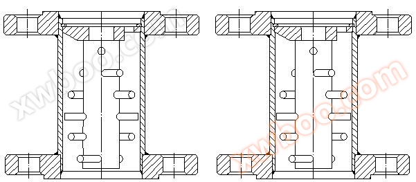
The structure of the magnetic filter is shown in the figure:

Magnetic filter structure lined with PTFE magnetic filter structure

8、 Limit switch alarm device
The limit switch alarm device in the indicator is composed of an induction head, aluminum sheet, etc. The induction head is installed at a position that can be cut by the aluminum sheet on the pointer shaft. By changing the position of the induction head, the limit value can be set arbitrarily. The induction head outputs a signal to the metal rotor flow indicator controller.
Technical Parameter
1. Power supply: 24V AC ± 10%
2. Power consumption: ≤ 3W
3. Working temperature: -25 ℃~60 ℃
4. Output contact capacity: 24VAC 3A
Wiring diagram

The change of alarm point requires opening the front cover, loosening the screw of the small pointer on the dial, adjusting it to the desired position, then tightening the screw, and finally installing the front cover.
10Design selection and ordering instructions
1. According to whether the measured fluid is gas or liquid, use a gas or liquid metal tube float flowmeter correctly.
2. If the tested fluid is non corrosive, choose the ordinary type, and if it is corrosive, choose the corrosion-resistant type.
3. Please indicate the name, flow rate, pipe diameter, working pressure, temperature, density, viscosity, and other information of the tested medium when placing an order. Our company adjusts the scale according to the density and other requirements provided by the user, and produces a special flow scale.
4. Select appropriate specifications and varieties based on the measurement range and application scenarios of the fluid being tested. If there are special requirements for flow meters, please contact the company or contact the sales department via email.