-
E-mail
692362183@qq.com
-
Phone
15926773610
-
Address
Hangrong Science and Technology Park, Longchi Industrial Zone, Macheng City, Hubei Province
Product Categories
Hubei Hangrong Electric Co., Ltd


Linkage between LMX06-PS05 laser rangefinder and photoelectric switch
NegotiableUpdate on 01/07
- Model
- Nature of the Manufacturer
- Producers
- Product Category
- Place of Origin
Overview
The linkage between LMX06-PS05 laser rangefinder and photoelectric switch can achieve more complex and precise control logic. Through reasonable design and programming, the advantages of both can be combined and applied to various industrial automation and measurement scenarios.
Product Details
Linkage between LMX06-PS05 laser rangefinder and photoelectric switch
LMX06-PS05Laser rangefinders and photoelectric switches are commonly used equipment in the fields of industrial automation and measurement. Laser rangefinders are mainly used for precise distance measurement, while photoelectric switches are used to detect the presence or absence of objects. Linking the two can trigger actions or perform more complex control logic under specific conditions.
1、 Overview of Working Principle
Firstly, we need to understand the basic working principle of laser rangefinders. Laser rangefinders usually use two methods to measure distance: pulse method and phase method. The process of pulse distance measurement is that the laser emitted by the rangefinder is reflected by the measured object and then received by the rangefinder, which simultaneously records the round-trip time of the laser. Half of the product of the speed of light and round-trip time is the distance between the rangefinder and the object being measured. This principle enables laser rangefinders to measure distance accurately and with high precision.
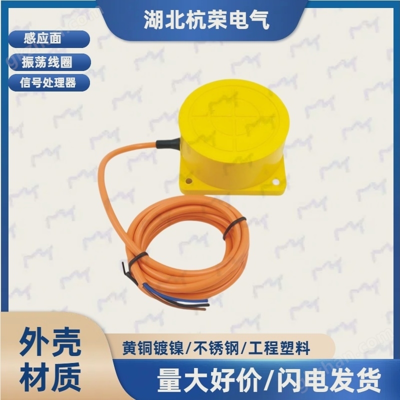
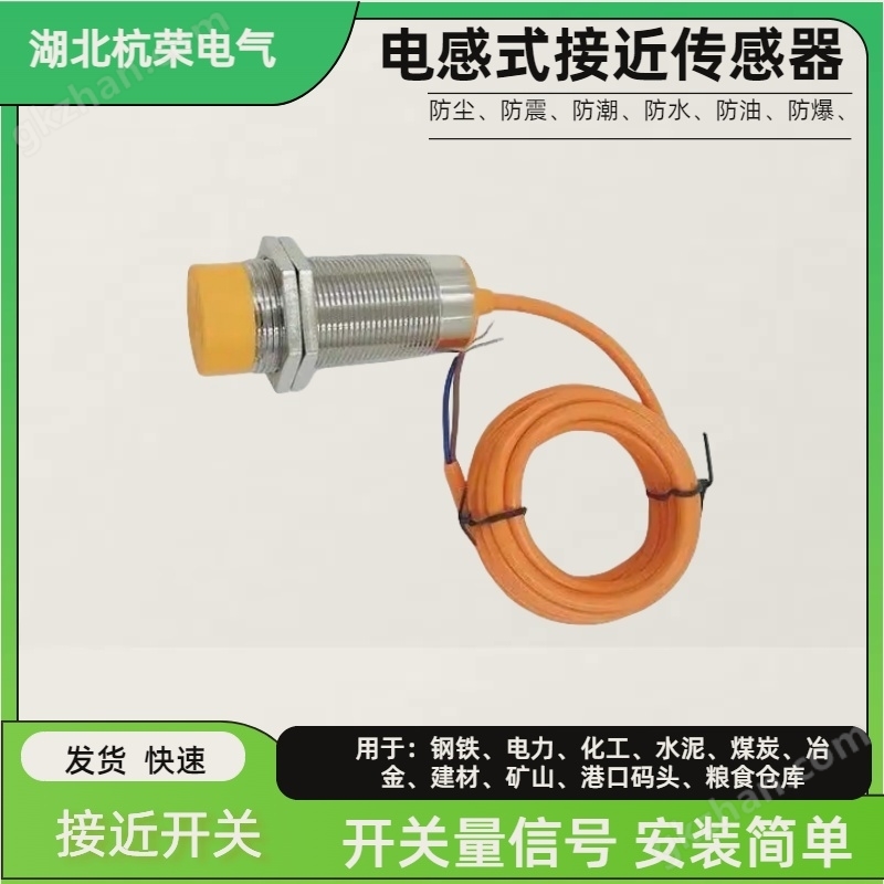
LMX06-PS05The photoelectric switch works by detecting the obstruction or reflection of light beams by objects. When an object enters the detection area of the photoelectric switch, the photoelectric switch will emit a signal, usually an electrical signal, indicating the presence of the object. The response speed of photoelectric switches is very fast, suitable for rapid detection and control.
2、 Linkage plan
Translate into EnglishLMX06-PS05The linkage between laser rangefinder and photoelectric switch can be achieved through the following methods:
1. Distance triggered photoelectric switch: The laser rangefinder can set a threshold distance. When the distance between the measured object and the rangefinder is less than or greater than this threshold, the laser rangefinder can send a signal to the photoelectric switch to trigger it. For example, when an object approaches a specific distance, a laser rangefinder detects this distance and sends a signal to a photoelectric switch, which then triggers and may be used to initiate a mechanical action or sound an alarm.
2. Photoelectric switch assisted laser rangefinder: The photoelectric switch can be used to detect the presence of an object and then notify the laser rangefinder to start measuring. For example, on a production line, when a photoelectric switch detects an object passing through, it sends a signal to a laser rangefinder, which then begins measuring the distance or size of the object.
3. Combined use to improve accuracy: In some applications, laser rangefinders may be affected by environmental factors such as light, dust, etc. At this point, a photoelectric switch can be used as an auxiliary means to help the laser rangefinder locate objects more accurately. For example,LMX06-PS05The photoelectric switch can first detect the approximate position of the object, and then the laser rangefinder can make precise measurements.
3、 Implementation steps
To achieve the linkage between laser rangefinder and photoelectric switch, the following steps are usually required:
1. Hardware connection: Firstly, the laser rangefinder and photoelectric switch need to be connected to the same control system, such as PLC (Programmable Logic Controller) or microcontroller. This usually involves electrical connections to ensure that signals can be transmitted correctly.
2. Programming logic: Write programs in the control system to define the linkage logic between the laser rangefinder and the photoelectric switch. For example, when the photoelectric switch detects an object, the program will command the laser rangefinder to start measuring and perform corresponding actions based on the measurement results.
3. Parameter setting: Set the measurement parameters of the laser rangefinder according to specific application requirements, such as measurement range, accuracy, etc. At the same time, it is also necessary to set the sensitivity and detection distance of the photoelectric switch.
4. Testing and debugging: After the system integration is completed, conduct testing and debugging to ensure that the linkage function works properly. This includes checking whether the signal transmission is correct, whether the measurement results are accurate, and whether the linkage logic meets expectations.
4、 Precautions
in useLMX06-PS05When using a laser rangefinder and photoelectric switch, the following points should be noted:
1. Safe operation: The laser emitted by the laser rangefinder may cause harm to the eyes, so direct eye contact with the laser beam should be avoided during operation.
2. Environmental impact: Laser rangefinders and photoelectric switches may be affected by environmental factors such as temperature, humidity, dust, etc. When designing a system, these factors should be considered and corresponding protective measures should be taken.
3. Regular maintenance: In order to ensure the long-term stable operation of the system, it is necessary to regularly inspect the laser rangefinder andLMX06-PS05Maintain and calibrate the photoelectric switch.

Conclusion
LMX06-PS05The linkage between laser rangefinder and photoelectric switch can achieve more complex and precise control logic. Through reasonable design and programming, the advantages of both can be combined and applied to various industrial automation and measurement scenarios. When implementing linkage schemes, careful consideration should be given to hardware connections, programming logic, parameter settings, and secure operations to ensure the reliability and accuracy of the system.
CK3-X1 magnetic switch
WZLXJ-QG50 valve position switch position signal feedback device
YG5-5001-EG overhead crane alarm
HFRLB-1 pull rope switch explosion-proof
STSG-01 Sound and Light Alarm AC220V Red
XKP-ET-CA2 alarm
Tear detector ZL-B-1400 sensor control box
Flash alarm AOXXS08H8NA0
Similar Product Recommend