-
E-mail
1987440091@qq.com
-
Phone
19901806598
-
Address
No. 77 Shenglong Road, Jiufu Development Zone, Songjiang District, Shanghai
Product Categories
Shanghai Prima Electronics Co., Ltd

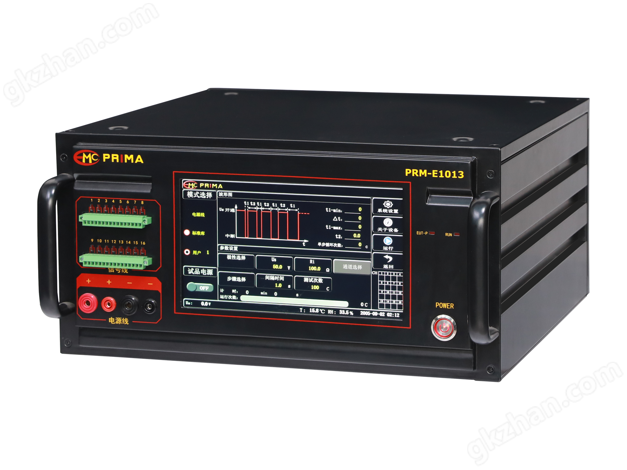
Industrial automatic square wave pulse generator
NegotiableUpdate on 01/07
- Model
- Nature of the Manufacturer
- Producers
- Product Category
- Place of Origin
Overview
The industrial automatic square wave pulse generator is manufactured by the technical department of Shanghai Prima Company in strict accordance with customer industry requirements, used to evaluate the performance of electrical and electronic equipment power lines and internal structures under high-energy transient pulse interference.
Product Details
Industrial automatic square wave pulse generatorIntroduction:
Generate different signals by utilizing different frequencies. For example, a square wave generator is used to generate sine signals (low frequency) with frequencies ranging from 20Hz to 200kHz. In addition to voltage output, some also have power output. So it has a wide range of applications, including testing or repairing the frequency characteristics, gain, and communication frequency band of low-frequency amplifiers in various electronic instruments and equipment, as well as serving as an external modulation signal source for high-frequency signal generators.
Use of industrial automatic square wave pulse generator
1. Connect the signal generator to an AC 220V, 50Hz power supply, press the power switch, the indicator light will turn on, turn on the power, and the switch indicator light will display. Choose the appropriate signal output form (square wave or sine wave).
2. Press the selection function switch for the desired waveform. When a pulse wave needs to be output, pull out the duty cycle adjustment switch and adjust the duty cycle to obtain a stable and clear waveform. At this time, the frequency is 1/10 of the original, and the duty cycle switch knob is pressed when in sine and triangular wave states. When a small signal output is required, press the attenuator to select the frequency range of the desired signal, press the corresponding level switch, and adjust the micro adjuster appropriately. At this time, the data indicated by the micro adjuster is multiplied by the level data to obtain the actual output signal frequency.
3. Adjust the power amplitude of the signal and select the appropriate attenuation level switch to obtain the desired power signal. Adjust the amplitude knob to the desired output amplitude. When DC level is required, pull out the DC offset adjustment knob to adjust the DC level offset to the desired level value. When in other states, press the DC offset adjustment knob, and the DC level will be zero.
4. Distinguish the positive and negative connection signal output plugs from the output terminals.
Similar Product Recommend