-
E-mail
2826683328@qq.com
-
Phone
18924378066
-
Address
Beizha Xifang Industrial Zone, Humen Town, Dongguan City
Product Categories
Dongguan Beituo Electromechanical Co., Ltd

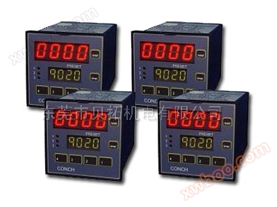
RKC thermostat CH102
NegotiableUpdate on 07/17
- Model
- Nature of the Manufacturer
- Producers
- Product Category
- Place of Origin
Overview
RKC thermostat CH102
Product Details
1.Product Model Explanation
CH□02 □□□□-□□*□□-□□
①② ③ ④⑤ ⑥⑦ ⑧9
①Control: F:PIDAction and active counting (reverse action)D:PIDActions and active counting (direct actions)
②input method
③Scale code: Refer to8Input scale table*
④Top manipulation output(OUT1)(Heating side):MRelay outputTThree terminal bidirectional controllable switchVVoltage pulseB: Current(4arrive20Milliampere direct current)
GZero crossing (used for three terminal bidirectional controllable drive)
⑤Second control output(OUT2)(Refrigeration side)
⑥Alarm Output[ALM1]
N: No alarmsA: High error alarmB: Low error alarmC: High error/Low AlarmDJoint AlertEHigh error alarm and continue
FLow error alarm and continueG: High error/Low alarm and continueH: High progress alarmLLow progress alert and continueJ: Low Progress Alert
KHigh progress alarm and continue
7Alarm output[ALM1]
N: No alarmsA: High error alarmB: Low error alarmC: High error/Low AlarmDJoint AlertEHigh error alarm and continue
FLow error alarm and continueG: High error/Low alarm and continueH: High progress alarmLLow progress alert and continueJ: Low Progress Alert
KHigh progress alarm and continue
8Communication function:N: No communication function 5:RS-485(2-Line system)
9Waterproof and dustproof layout:N: No waterproofing/Dustproof layout 1: Waterproof/Dustproof layout
2.device
2.1 Equipment conditions
※The ambient temperature shall not be lower than0Degree or not exceeding50linear measure※The environmental humidity is not lower than45%Or not exceeding85%RH
※No corrosive or flammable gases.※Local areas without water, oil, chemicals, or steam splashing
※No excessive induction of noise, static electricity, or magnetic field.※Non thermal aggregation constitutes thermal radiation
2.2 scale
|
Instrument model |
wide*tall*deep |
holeMM |
Instrument model |
wide*tall*deep |
holeMM |
|
CH102 |
48*48*100 |
45*45 |
CH402 |
48*96*100 |
45*92 |
|
CH502 |
96*48*100 |
92*45 |
CH702 |
72*72*100 |
68*68 |
|
CH902 |
96*96*100 |
92*92 |
|
|
|
3.Warning
3.1 Wiring precautions
(1)Regarding thermocouple input, use specific compensation lines.
(2)Regarding the input of thermal resistance, low resistance wires are used, and there is no resistance difference between the three wire ends.
(3)Bypass the input signal line around the external power supply, electrical equipment power supply, and load line to avoid noise induction.
(4)Regarding current input, it must be supplied by the input terminal250European resistor(±0.02%±10ppnm, 0.25W).
3.2 Exterior wiring
Power supply voltage:90to264VCommunication Electricity50/60HZ、≤7W
Alarm output levelRelay connection output:250Communication and electricity,1An (resistive load)
Control output levelRelay connection output:250Communication and electricity,3An (resistive load)
Voltage pulse output:0/12Voltage direct current (load resistance)600Europe or more)
Current output:4to20MADirect current (load resistance)600Europe or less)
Zero crossing output (for three terminal bidirectional control drive): used for zero crossing triggering
4.Panel Explanation
1) Measured values(PV)Display unit: Display the measured values(PV)Different parameter symbols that appear on the surface
2)Set numerical values(SV)Display unit Display the set values(SV)Different setting parameters that show the appearance
3)Indicator light**
Active setting indicator light(AT)Shine brightly when actively scheduled
Control output indicator light(OUT1)When the control output is turned on, it lights up
Alarm output indicator light(ALM1)When the alarm is triggered, it lights up
Auxiliary output indicator light(OUT2)When the auxiliary output is turned on, it lights up
4)Settings key(SET): Used for input/Retrieve the parameters and press for more than two seconds to read the data from Table 2
5)Transformation andR/SKey(R/S)Transform numbers (transform keys) when making changes to settings, used to select operations/Suspend function
6)Descent key: used to descend numbers
7)Up key: used to raise numbers
5.Present the form and condition
5.1Each form of open program
Turn on the power supply→Display input method→Display input scale (approximately displayed)4Seconds)→If there is no response time after pressing the button, exceed1Minutes, appearance repliedPV/SVShow the formal condition.
Parameter setting format
5.2 Detailed explanation of each form:PVShow the situation/SVSetting data
Press every timeSETThe condition and data displayed when the key is pressed:
Table 2#1Factory setting values
|
sign |
title |
Set scale |
describe |
#1 |
|
AL1 |
Alarm(ALM1) |
Error alert, progress alert SVAlert:-1999to+1999Degree or-199.9to+999.9linear measure |
Set alarm values Alarm micro gap:2perhaps2.0linear measure |
50(50.0) |
|
AL2 |
Alarm(ALM2) |
Error alert, progress alert SVAlert:-1999to+1999Degree or-199.9to+999.9linear measure |
Set alarm values Alarm micro gap:2perhaps2.0linear measure |
50(50.0) |
|
ARU |
Self tuning(AT) |
0:ATCompleted or paused 1:ATbeginning |
Open it up/Closed self-tuning function |
0 |
|
SRU |
Coordinating oneself(ST) |
0:STpause 1:ATbeginning |
Open it up/Sealing itself has a coordinating function |
0 |
|
P |
Share size(P) |
1(0.1)To the other end of the fluctuation or9999(999.9)Degree |
existPI,PDperhapsPIDSet during homework manipulation.*ON/OFFThe action is set to0(0.0)Start the control effect from time to time. Micro differential gap:2(0.0)Degree |
30(30.0) |
|
I |
Integral Time |
1to3600second *set to0Second hourPDControl effect |
Set the moment of integration effect when the error presented during the constraint share cooperative manipulation process is set |
240 |
|
D |
Differential time |
1to3600second *set to0Second hourPDControl effect |
By guessing and adjusting the output settings to avoid the differential timing of wrinkles, the stability of the control can be improved |
60 |
|
Ar |
Parameters(Ar) |
0to100%*1 |
In proactive settingsATafter |
25 |
|
T |
Share cooperation period(T) |
1to100Second (cannot be set to0)*2 |
Set the control output cycle |
20 |
|
PB |
PVError(PB) |
-1999to+9999Degree or-199.9to+999.9linear measure |
Sensor adjustment is obtained by adding the error value to the measured value(PV) |
|
|
LCK |
Set data determination function(LCK) |
see*3 |
Make the setting data adjustable/Not adjustable |
0000 |
*1The reference value cannot be inPIDInternal craftsmanship input is“AT”The self-tuning function is actively set.
*2Relay20Second, voltage pulse output, zero crossing output2In seconds.
*3Set data to determine detailed level selection
|
set up |
Detailed determination of level |
|
0000 |
SVAnd the parameters can be set |
|
0001 |
as long asSVAnd alarms(ALM1,ALM2)Can be set |
|
0010 |
As long as the alarm is removed(ALM1,ALM2)External adjustable items can be set |
|
0011 |
as long asSVOther settings can be set |
|
0100 |
as long asSVCan be set |
|
0101 |
As long as the alarm is triggered(ALM1,ALM2)Can be set |
|
0110 |
As long as it is removedSVAnd alarms(ALM1,ALM2)External adjustable items can be set |
|
0111 |
SVAnd the parameters cannot be set |
lEach determined setting item can only be monitored.
6.Self tuning(AT)Function
The active operation function refers to actively measuring, calculating, and setting the most suitable onesPIDConstant.
After turning on the power, this function will start when the temperature rises steadily at any stage of operation.
■ATRequirement for functional activation
Under the condition that all of the following conditions are satisfiedATFunction activated.
·StartingATFunction before removalPIDComplete all other parameter settings except for parameter settings.·ensureLCKThe functions were not activated together.
■ATFunction paused
If any of the following situations occur,ATFunction pause:
·equalSVWhen making changes·equalPVWhen the error value is changed·equalSVoperate/The stop function switch is turned to“discontinue”time·PVWhen presenting anomalies
·Power outage exceeds20Millisecond time·supposeATAfter the function is activated9Not closed within the hour.
|
filler |
●Once presented, makeATThe situation where the function is temporarily suspended,ATThe function is immediately paused and changed toPIDControl.
this momentPIDConstant still remains openATSame function before. Other than that, even ifATCompletion, i.e. actively transitioning toPIDControl.
●If there are doubts caused by the control system, it cannot be usedATFunction. In this situation, set each parameter to match the target being controlled.
7. Fault manifested
■Fault manifestation: Err:Incorrect data input and writing, etc
■Exceeding the upper limit and exceeding the lower limit:OOOO:The measured(PV)The value exceeds the upper limit of the input scale
UUUU:The measured(PV)The value exceeds the lower limit of the input scale
8. Input scale table
|
Input type |
Comde |
Input type |
Comde |
Input type |
Comde |
|||
|
K |
0-200℃ |
K:01 |
S*1 *1 |
0-1600℃ |
S:01 |
Pt100 |
-199.9-+649.0℃ |
D:01 |
|
0-400℃ |
K:02 |
0-1769℃ |
S:02 |
-199.9-+200.0℃ |
D:02 |
|||
|
0-600℃ |
K:03 |
B*1 *1 |
0-1800℃ |
B:01 |
-100.0-+50.0℃ |
D:03 |
||
|
0-800℃ |
K:04 |
0-1820℃ |
B:02 |
-100.0-+100.0℃ |
D:04 |
|||
|
0-1000℃ |
K:05 |
E |
0-800℃ |
E:01 |
-100.0-+200.0℃ |
D:05 |
||
|
0-1200℃ |
K:06 |
0-1000℃ |
E:02 |
0.0-50.0℃ |
D:06 |
|||
|
0-1372℃ |
K:07 |
N |
0-1200℃ |
N:01 |
0.0-100.0℃ |
D:07 |
||
|
0-100℃ |
K:13 |
0-1300℃ |
N:02 |
0.0-200.0℃ |
D:08 |
|||
|
0-200℃ |
K:14 |
*2 *2 T |
-199.9-+400.0℃ |
T:01 |
0.0-300.0℃ |
D:09 |
||
|
0-450℃ |
K:17 |
-199.9-+100.0℃ |
T:02 |
0.0-500.0℃ |
D:10 |
|||
|
0-500℃ |
K:20 |
-100.0-+200.0℃ |
T:03 |
0.0-400.0℃ |
D:20 |
|||
|
J |
0-200℃ |
J:01 |
0.0-350.0℃ |
T:04 |
Pt100 |
-199.9-+649.0℃ |
P:01 |
|
|
0-400℃ |
J:02 |
W5Re/ W26Re |
0-2000℃ |
W:01 |
-199.9-+200.0℃ |
P:02 |
||
|
0-600℃ |
J:03 |
0-2320℃ |
W:02 |
-100.0-+50.0℃ |
P:03 |
|||
|
0-800℃ |
J:04 |
PLII |
0-1300℃ |
A:01 |
-100.0-+100.0℃ |
P:04 |
||
|
0-1000℃ |
J:05 |
0-1390℃ |
A:02 |
-100.0-+200.0℃ |
P:05 |
|||
|
0-1200℃ |
J:06 |
0-1200℃ |
A:03 |
0.0-50.0℃ |
P:06 |
|||
|
0-450℃ |
J:10 |
*2 U*2
|
-199.9-+600℃ |
U:01 |
0.0-100.0℃ |
P:07 |
||
|
0-600℃ |
J:20 |
-199.9-+100℃ |
U:02 |
0.0-200.0℃ |
P:08 |
|||
|
*1 R*1 *1 |
0-1600 |
R:01 |
0.0-400.0℃ |
U:03 |
0.0-300.0℃ |
P:09 |
||
|
0-1769 |
R:02 |
L |
0-400℃ |
L:01 |
0.0-500.0℃ |
P:10 |
||
|
0-1350 |
R:04 |
0-800℃ |
L:02 |
0.0-400.0℃ |
P:20 |
|||
|
0-5V/DC |
1999- 9999 |
4:01 |
0-20mADC |
1999- 9999 |
6:01 |
|
|
|
|
1-5V/DC |
5:01 |
4-20mADC |
7:01 |
|
|
|
||
The relevant product models are:CH402|CD901|RH400|RKC thermostat