-
E-mail
jack.shi@scitest.cn
-
Phone
13381923051
-
Address
Room 1001, Building 32, Lane 1051, Shenbin Road, Shanghai
Product Categories
Shanghai Jiulichuan Trading Co., Ltd

Price of thyristor tester
NegotiableUpdate on 02/19
- Model
- Nature of the Manufacturer
- Producers
- Product Category
- Place of Origin
Overview
The price of the thyristor tester is $r $n, suitable for parameter testing of various reverse blocking thyristors, reverse conducting thyristors, and bidirectional thyristors. This tester has advanced design, reasonable structure, and easy operation.
Product Details
Price of thyristor tester working conditions
Power supply voltage: AC 220V ± 10% 50HZ
Working temperature: 0-40 ℃
2.8 Power consumption: less than 0.5KVA
2.9 Weight: Approximately 15Kg
2.10 Dimensions: 440 × 440 × 150mm
3. Structural characteristics of thyristor volt ampere characteristic tester
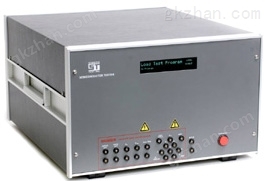
This instrument is a box type structure with a length and width of 440mm and a height of 150mm. The front panel of the instrument is equipped with a digital display meter, various control buttons (knobs), and wiring terminals. The rear cover of the instrument is equipped with a three core power socket, a fuse box (with a 2A/250V fuse tube), and oscilloscope wiring terminals.
4 Usage Methods
Technical Manual for 2 Thyristor Testers
Figure 4.1 Panel Diagram
4.1 Panel component functions (see panel diagram)
4.1.1 "Power" switch
When this switch is turned on, the hidden indicator light lights up and the power is turned on.
4.1.2 "A, K" wiring terminals
Connect A to the anode of the tested device (or the T2 pole of the bidirectional thyristor), and connect K to the cathode of the tested device (or the T1 pole of the bidirectional thyristor).
4.1.3 "Protection current setting" dip switch current setting range is 1-99 milliamps.
This dip switch is divided into two or ten positions, with one position set to 0-9 digits and ten position set to 0-9 digits.
The combination of one and ten digits forms a set of numbers, which is the protection current value, measured in milliamps.
For example, the number 28 indicates that when the measured current reaches 28 milliamps, the instrument automatically cuts off the current and voltage between A and K.
4.1.4 "Current (mA)" display table
Display the peak current of the tested device. Unit milliampere. The displayed current range is determined by the "current" range key.
4.1.5 "Current" range switch
When this key is pressed (20mA), the maximum current displayed on the "Current (mA)" meter is 20mA.
When this key is pressed (200mA), the maximum current displayed on the "Current (mA)" meter is 200mA.
4.1.6 "Voltage (V)" display table
Display the peak voltage of the tested device in volts. Read the voltage value in conjunction with the "Voltage" range key.
4.1.7 "Voltage" range switch
When this key is pressed (x 1), the value displayed on the "Voltage (V)" meter is the actual measured voltage, measured in volts.
When this key is pressed (× 10), the value displayed on the "Voltage (V)" meter is the actual measured voltage, measured in volts.
4.1.8 "Polarity" selection switch
Technical Manual for 3 Thyristor Testers
When this key is pressed (forward), terminal A is the positive pole of the power supply and K is the negative pole. When pressed in (reverse), terminal A is the negative pole of the power supply and K is the positive pole.
4.1.9 "Reset (Single)" switch
After the output current of this instrument exceeds the set value of the protection current, the "protection indicator" light will turn on. Press this switch to restore the instrument to its normal working state (the "protection indicator" light will turn off).
4.1.10 "Protection indicator" light
When the instrument is overcurrent protected, the "protection indicator" light is on. At this point, the instrument output returns to zero.
4.1.11 "Voltage Adjustment" Button
Clockwise adjustment increases the voltage between A and K, while counterclockwise adjustment decreases the voltage between A and K.
4.2 Connecting the power cord
This instrument needs to be connected to a 220V single-phase power supply with a ground wire. When wiring, the following two points should be noted:
4.2.1 The grounding terminal of the three wire power plug should be reliably grounded to ensure the measurement accuracy of the instrument and the safety of the operator. Otherwise, when the "voltage adjustment" button is reset to zero (counterclockwise to the bottom), the "current (mA)" and "voltage (V)" meters cannot return to zero, and when unloaded (without connecting the tested component), the current value increases with the increase of voltage. The ground wire referred to must be the ground referred to in electrical terminology and cannot be replaced by a water pipe or the like.
4.2.2 Although the grounding terminal of the power cord is well grounded, when the "voltage adjustment" button is reset to zero (counterclockwise to the bottom), the "current (mA)" and "voltage (V)" meters still cannot be reset to zero. The live and neutral wires of the 220V power supply can be swapped.
4.3 Connecting the oscilloscopePrice of thyristor tester
As needed, this instrument can be connected to a DC coupled oscilloscope to observe the V-I curve (if the oscilloscope's power supply has a grounding wire, the grounding must be disconnected). The back cover of this instrument is equipped with terminals for connecting the oscilloscope. When wiring, connect the X, Y, and ⊥ terminals of the oscilloscope to the corresponding X, Y, and ⊥ terminals of the instrument's wiring terminals.
4.4 Testing steps
4.4.1 Adjust the "voltage adjustment" button counterclockwise to the end.
4.4.2 Turn on the "power" switch.
4.4.3 Select a set of required values for the "protection current setting" switch, such as 2mA.
4.4.4 Connect the tested device to the terminal block.
4.4.5 "Current" range switch, select the desired position. To ensure measurement accuracy, the 20mA range is preferred. If the measured current is greater than 20mA, the "current (mA)" display will show "1". At this time, the 200mA level should be selected.
4.4.6 Select the desired position for the "voltage" range switch. In order to ensure measurement accuracy, it is preferred to select the X 1 level.
If the measured voltage is greater than 2000V and the "Voltage (V)" display shows "1", then the X 10 level should be selected.
4.4.7 Press the "reset" switch (if the "protection indicator" light is off, do not press this button).
4.4.8 Adjust the "Voltage Adjustment" button clockwise, while reading the values from the "Current (mA)" and "Voltage (V)" display tables.
After the 4.4.9 test is completed, the "voltage adjustment" button must be adjusted counterclockwise to the end.
4 Technical Manual
5 Precautions
When the voltage value between A and K reaches 3000V (5000V for 023B) or above, its duration cannot exceed 30 seconds.
Do not press the polarity selection switch when the voltage between A and K is not zero.
5.3 There is high voltage between output terminals A and K and the ground of the casing, and it is strictly prohibited to touch them during operation.