-
E-mail
2355335611@qq.com
-
Phone
19942710493
-
Address
Room 602, No. 482 Xinglinwan Road, Jimei District, Xiamen City
Product Categories
Xiamen Yingyi Automation Technology Co., Ltd


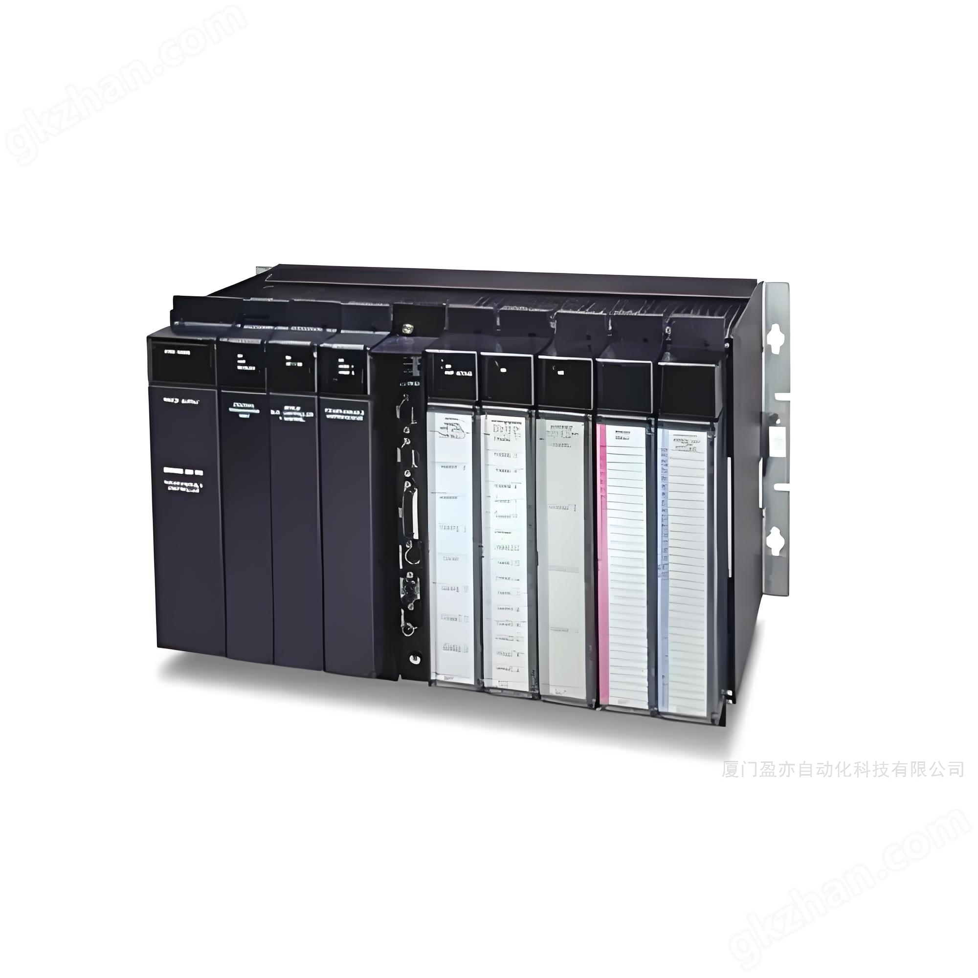
General Electric IC200 Control System Module
NegotiableUpdate on 01/07
- Model
- Nature of the Manufacturer
- Producers
- Product Category
- Place of Origin
Overview
The General Electric IC200 control system module is used to store program code, intermediate calculation results, and necessary parameter settings. The IC200MDL650 control system module is typically equipped with non-volatile storage media such as flash memory or EEPROM to ensure that important data can be retained even after power failure.
Product Details
1、 Working principle
The IC200MDL650 control system module is the basic functional unit of the entire control system, usually composed of the following key components:
1. Input interface: Receive signals from sensors or other external devices. These signals can be digital quantities (such as switch status) or analog quantities (such as temperature, pressure). The input interface is responsible for converting these physical signals into a form suitable for processing by the processor.
2. Central processing unit (CPU): responsible for executing pre programmed logic algorithms. It calculates based on the received input signal and determines the corresponding output action. It also supports multitasking and real-time response capabilities.
3. Memory: used for storing program codeGeneral Electric IC200 Control System ModuleIntermediate calculation results and necessary parameter settings. The IC200MDL650 control system module is typically equipped with non-volatile storage media such as flash memory or EEPROM to ensure that important data can be retained even after power failure.
4. Output interface: Convert the control signals generated by the CPU into the physical form required to drive the actuator, such as voltage, current, or pulse width modulation (PWM). The output interface also needs to have a certain protection mechanism to prevent damage to the system caused by overload or short circuit.
5. Communication interface: Many control system modules support the ability to exchange data with other devices or networks. Common communication protocols include RS-232/485, CAN bus, Ethernet, and wireless communication standards such as Wi Fi, Zigbee, etc., which make distributed control systems possible.
2、 Type and Characteristics
1. Programmable Logic Controller (PLC) module: PLC is one of the common control system modules,General Electric IC200 Control System ModuleWidely used in the field of industrial automation. They have a sturdy and durable design that allows them to operate stably for long periods of time in harsh environments. PLC modules typically support ladder programming language, which is easy to understand and maintain.
2. Microcontroller module: A control system module based on a microcontroller (MCU) is suitable for scenarios that require high customization. The microcontroller module has a compact size, low power consumption, and high cost-effectiveness, making it very suitable for embedded system development. Developers can write firmware in C/C++or assembly language to implement specific functions.
3. Application specific integrated circuit (ASIC) modules: ASIC modules designed for certain applications can provide high performance and efficiency. Although the development cycle is long and the cost is high, once put into production, ASIC modules can significantly reduce costs and improve reliability in large-scale production.
4. Field Programmable Gate Array (FPGA) module: FPGA is a solution between general-purpose processors and ASICs. It allows users to define circuit structures through Hardware Description Language (HDL), enabling highly flexible designs. FPGA modules are particularly suitable for applications that require high-speed parallel processing, such as image recognition, video encoding, etc.
3、 Application scenarios
1. Industrial Automation: In factory automation systems, the IC200MDL650 control system module is used to monitor the status of various equipment on the production line and automatically adjust the robot's motion trajectory or valve opening according to preset conditions. This not only improves production efficiency, but also reduces the likelihood of human errors occurring.
2. Building Automation: The intelligent building management system utilizes the IC200MDL650 control system module to coordinate the operation of multiple subsystems such as lighting, air conditioning, and security. For example, automatically adjusting the brightness of lights based on indoor lighting intensity, or optimizing air conditioning cooling/heating strategies based on indoor and outdoor temperature differences, can improve living comfort and save energy consumption.
3. Traffic management system: The urban traffic signal control system achieves dynamic regulation by integrating multiple control system modules. Based on real-time traffic information, the system can flexibly adjust the duration of traffic lights to alleviate congestion. In addition, it is also used in railway dispatch systems to ensure the safe operation of trains.
4. Medical equipment: Modern medical devices such as pacemakers and ventilators require precise control systems to maintain stable vital signs of patients. These devices are equipped with high-performance control system modules that can quickly respond to physiological changes and make corresponding adjustments.
4、 Configuration and Debugging Methods
1. Hardware connection: Connect the power cord, grounding wire, and signal wire correctly according to the manufacturer's instructions. Pay attention to checking whether the contact between each terminal is good, to avoid signal loss or fluctuation caused by poor contact.
2. Software configuration: Create corresponding control logic in the PLC programming environment and set the correct address mapping relationship. In addition, it is necessary to define parameters such as the format, range, and resolution of input/output signals. For complex control systems, it is recommended to use modular programming methods for easy maintenance and expansion in the future.
3. Test validation: Before being officially put into use, offline testing should be conducted to verify whether the module's functionality is normal. You can manually modify the input signal value and observe whether there is a corresponding change in the actual output signal; You can also use an oscilloscope to measure the waveform of the output port to ensure that the values fall within a reasonable range.
4. Troubleshooting: If abnormal system behavior is found, first check for hardware faults (such as open circuits, short circuits). Check if there are any issues with the PLC program logic, especially those related to logical judgment. If necessary, you can refer to the technical support documents provided by the manufacturer for more assistance.


